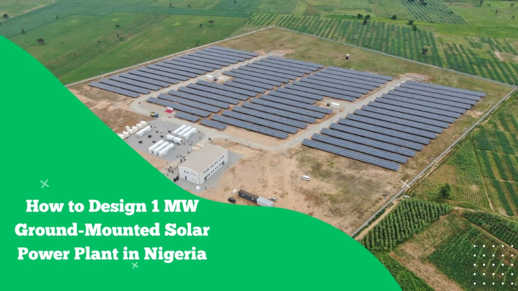
A “1 MW solar plant” sounds simple until you try to build it in Nigeria—where land titles can be messy, the grid is often weak, approvals can be misunderstood, and operations must survive dust, heat, rain, theft risk, and unstable evacuation.
This post walks through a practical, engineering-first approach to designing a 1 MW ground-mounted PV plant in Nigeria—from land and layout to inverter sizing, grid connection, and the operational realities that shape the design.
1) Start by defining what “1 MW” means
In real projects, “1 MW” can mean:
- 1 MWp (DC): total PV module nameplate (e.g., 1,000 kWp)
- 1 MWac (AC): inverter export limit (e.g., 1,000 kW at the point of interconnection)
Most EPC designs in Nigeria target something like:
- 1.0 MWac export with 1.2–1.5 MWp DC (DC/AC ratio 1.2–1.5) to improve energy yield and inverter utilization under real irradiance/temperature conditions.
Decision to lock early: Are you being paid for installed DC capacity or exported AC capacity? That determines everything downstream—module count, inverter rating, transformers, metering, and permits.
2) Project pathway choice (this affects licensing + design)
A 1 MW plant in Nigeria typically falls into one of these buckets:
- A) Captive / Private network (C&I)
You generate for an industrial or commercial site (or a campus), possibly hybridized with gensets/batteries.
- B) Mini-grid (isolated or interconnected)
Nigeria’s mini-grid framework is commonly referenced as having a capacity cap around 1 MW per site, with public discussion about raising it.
(If you’re right at 1 MW, you must be extremely clear whether you’re “at the cap” on paper vs in reality.)
- C) Embedded generation / Disco interconnection
You interconnect to a distribution network and export into a Disco system; then distribution code/grid code compliance, protection, and metering become central.
Practical Nigerian lesson: pick the pathway before you design the electrical architecture. People often do it backwards and pay twice.
3) Land acquisition and site viability (Nigeria-specific reality check)
3.1 How much land do you need?
For ground-mount, a rough planning range is:
- 1 MWp: ~ 1.5 to 2.5 hectares (15,000–25,000 m²)
The spread depends on:
- Tilt angle + row spacing (to reduce shading)
- Tracker vs fixed-tilt (trackers increase spacing and cost/complexity)
- Road widths, setbacks, drainage corridors, substation footprint
3.2 Land documentation and community risk
In Nigeria, the design must reflect the land reality:
- Confirm ownership and rights to build (survey, deed, governor’s consent where relevant)
- Community engagement is not “soft work”—it affects security and access during construction and operations
3.3 Environmental and physical constraints that change your civil design
Nigeria-specific constraints to check early:
- Flooding and drainage (many sites fail here)
- High water table (affects piles, earthing, trenching)
- Soil corrosion (coastal/saline regions)
- Wind exposure (taller structures increase risk)
If your site floods, your cable routing, inverter siting, and transformer plinth heights change.
4) Energy yield assumptions for Nigerian conditions
Your yield model depends on:
- Solar resource at site (typical Nigeria has strong irradiation, but it’s not uniform)
- High ambient temperatures (module output drops as temperature rises)
- Soiling (dust/harmattan can be a major loss driver)
A bankable design typically includes explicit allowances for:
- Soiling loss (site-dependent; can be significant without washing)
- Temperature loss
- Mismatch, wiring, inverter, transformer losses
- Availability (including grid outages/curtailment if grid-tied)
5) System sizing: modules, strings, and DC/AC ratio
5.1 Example module count (typical modern modules)
If you use 550 W modules for a 1.2 MWp DC field:
- 1,200,000 W ÷ 550 W ≈ 2,182 modules (round for stringing/layout)
5.2 String sizing (electrical constraints)
Your string length is determined by:
- Inverter MPPT voltage window
- Module Voc at the lowest expected temperature (yes, Nigeria is hot, but you still design for cold mornings/seasonal lows)
- Maximum DC input voltage (often 1000 V or 1500 V systems)
1500 V designs can reduce cable sizes and BOS cost, but require equipment compatibility and careful insulation/clearances.
6) Inverter sizing: string vs central (what works better in Nigeria?)
Option 1: String inverters (common for 1 MW)
Typical configuration:
- 10 × 100 kW or 5 × 200 kW string inverters
Benefits: - Better mismatch tolerance (multiple MPPTs)
- Easier staged maintenance (one inverter down doesn’t kill the plant)
- Often easier logistics and replacement in Nigeria
Risks:
- More units to secure, mount, and monitor
- More AC combining work
Option 2: Central inverter (less common at 1 MW)
Benefits:
- Centralized maintenance point
- Sometimes lower $/W at scale (but 1 MW is borderline)
Risks (Nigeria-relevant):
- If it fails, you lose most production
- Replacement lead times can be painful
Rule of thumb: For a 1 MW Nigerian project, string inverters are usually the safer O&M choice unless there’s a strong reason to centralize.
7) Layout and mechanical design (what engineers get wrong most)
7.1 Orientation and tilt
Nigeria is near the equator, so:
- Arrays generally face south (for northern hemisphere sites in Nigeria)
- Typical fixed tilt often lands around 10–15° depending on latitude, wind, and energy profile goals
7.2 Row spacing
Spacing is a trade:
- Tight spacing saves land
- Wider spacing reduces shading losses and makes O&M/cleaning easier
In Nigeria, wider spacing can pay off if:
- You expect heavy soiling and need frequent access for cleaning
- Vegetation growth is aggressive in rainy season and you need access for maintenance
7.3 Mounting selection
Common mounting options:
- Driven piles (fast, often cost-effective if soil permits)
- Ground screws (useful where driving is hard)
- Concrete foundations (more expensive; sometimes used for rocky soils)
Your geotechnical report is not a checkbox—it drives cost and schedule.
8) AC collection, transformer, and evacuation design
A typical 1 MW grid-tied architecture looks like:
- PV strings → inverters (400–800 Vac)
- Inverters → LV AC combiner/ACDB
- Step-up transformer (e.g., 0.415 kV to 11 kV or 33 kV depending on interconnection point)
- RMU/switchgear + protection
- Metering point
- Evacuation line to Disco/TCN interface (if required)
Protection and metering matter a lot for Nigeria
Distribution-connected generators must align with protection coordination and metering requirements under the relevant codes. The Nigerian Distribution Code discusses commercial/tariff metering and connection point requirements
9) Grid connection: studies you must design around
If you’re connecting to a Disco network or an interconnected mini-grid, expect requests for:
- Load flow / voltage rise assessment
- Fault level contribution
- Protection coordination (relays, settings, trip logic)
- Anti-islanding strategy
- Power quality (harmonics, flicker)
- SCADA/telemetry expectations (varies by operator)
Nigeria’s Grid Code sets technical expectations for grid users and embedded connections at a high level.
Design implication: you may need:
- Export limiting
- Reactive power capability / power factor control
- Plant controller (for multiple inverters)
- Dedicated protection relays and intertrip (case-dependent)
10) Compliance and certification: don’t ignore NEMSA
Beyond “it works,” you must plan for inspection and certification realities. NEMSA publishes certification schemes and guidelines touching renewable energy installation work and competency expectations.
Design impact:
- Proper single-line diagrams, protection philosophies, and as-builts
- Earthing and lightning protection done to standard, not improvisation
- Clear labeling, isolation points, safe access, and documented test results
11) Earthing and lightning protection (Nigeria’s storm reality)
Nigeria’s lightning activity is not something to hand-wave.
A robust design typically includes:
- Perimeter earth ring + equipment earth grids
- Bonding of module frames and structure
- Surge protection devices (DC and AC)
- Lightning risk assessment (especially for exposed sites)
- SPDs coordinated with inverter and switchgear requirements
12) SCADA, monitoring, and data (what separates “built” from “bankable”)
Even at 1 MW, treat monitoring as essential:
- Inverter monitoring + string-level (if available)
- Weather station (GHI/POA irradiance, module temp, ambient temp, wind)
- Revenue meter + check meter
- Alarm strategy that matches your security and O&M capacity
Nigeria-specific reason: when generation drops, you need to prove whether it’s soiling, grid outage, equipment fault, or curtailment.
13) Local operational challenges that must shape the design
13.1 Soiling + harmattan
Expect:
- Higher wash frequency during dust periods
- Abrasive dust risk if cleaning is poorly done
Design for: - Water access (borehole/storage) or dry-clean strategy
- Safe cleaning access lanes
13.2 Theft and vandalism risk
Design for:
- Cable routing strategy (buried depth, ducts, marker tapes)
- Minimized exposed copper
- Fencing, lighting, CCTV, guard house layout
- Tamper-resistant inverter and combiner placement
13.3 Grid unreliability
If grid-tied:
- Your plant may be “healthy” but unable to export due to outages or voltage issues
Design for: - Ride-through settings (as required)
- Export limit controls
- Clear event logging for disputes
13.4 Spares, FX, and lead times
Choose equipment families with:
- Local service presence or realistic support channels
- Replaceable parts availability
- Standard ratings (avoid exotic components unless necessary)
14) A practical “design package” checklist (what you should produce)
A solid Nigerian 1 MW design package usually includes:
- Basis of Design (BoD) + site constraints
- Yield report and loss diagram
- GA layout: module tables, access roads, drainage plan, fencing
- Electrical SLD: DC, AC, MV, protection, metering
- Stringing schedule + cable sizing + voltage drop calculations
- Earthing and lightning protection design
- Protection coordination study (grid-tied)
- Interconnection design: transformer sizing, MV switchgear, metering
- SCADA/monitoring architecture
- O&M concept: cleaning plan, spares list, preventive maintenance schedule
- Commissioning test sheets + as-built documentation plan
Key takeaway
In Nigeria, designing a 1 MW ground-mounted solar plant is less about textbook PV sizing and more about designing for permitting pathway, grid weakness, security risk, and maintainability under dust/heat/rain realities—while still meeting code and inspection expectations.