
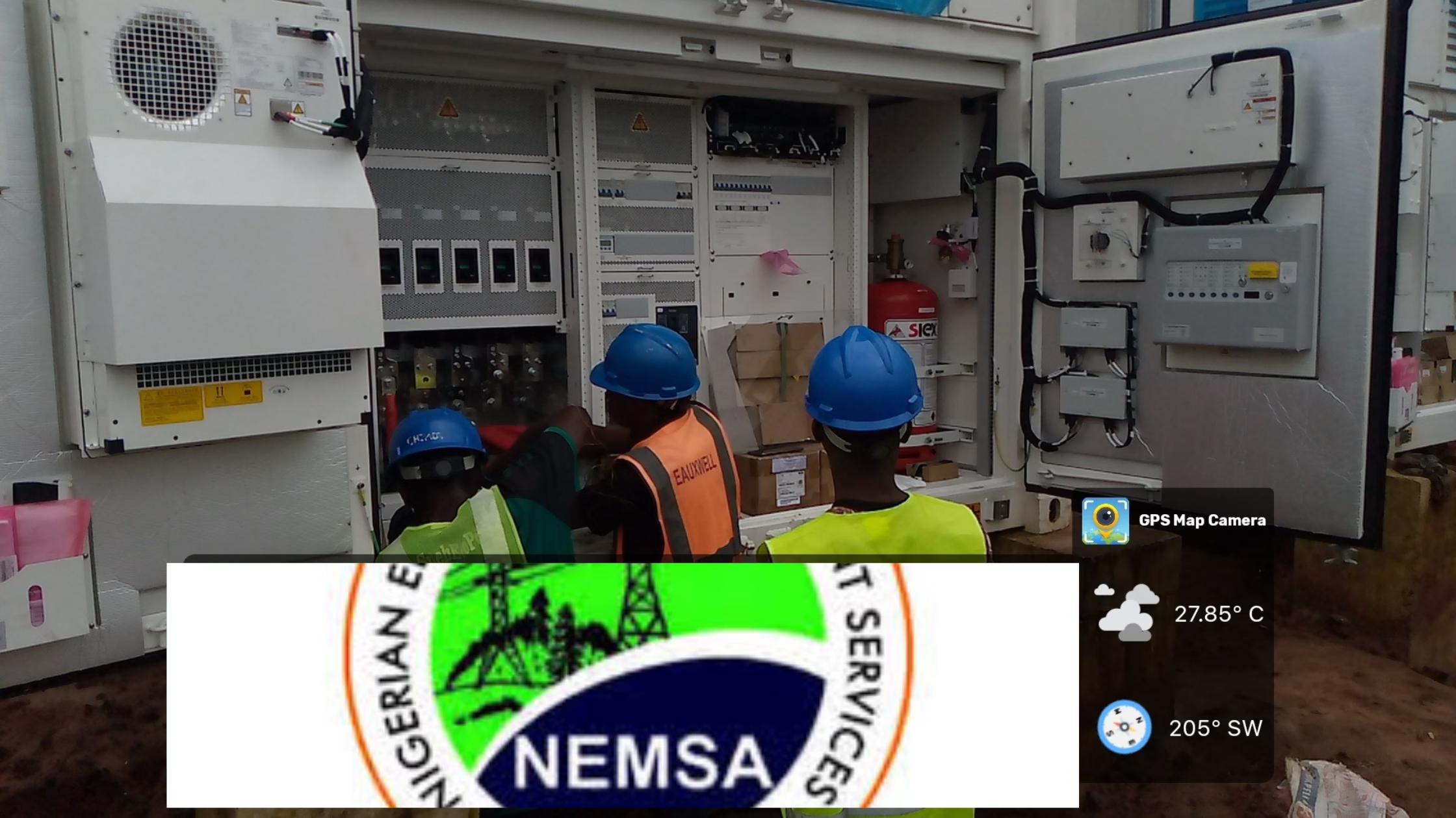
As Nigeria expands its renewable energy footprint, solar hybrid power plants are becoming critical parts of the nation’s energy infrastructure. But before any solar project can be connected to the national grid or officially commissioned, it must first pass through one crucial stage — NEMSA inspection and certification.
If you’re a Lead Resident Engineer, Project Manager, or EPC contractor, this guide will show you everything you need to prepare for a NEMSA site visit, including a comprehensive pre-inspection checklist designed specifically for large-scale solar hybrid projects.
What is NEMSA and Why the Inspection Matters
The Nigerian Electricity Management Services Agency (NEMSA) is the authority responsible for ensuring that all electrical installations in Nigeria are safe, technically sound, and compliant with national standards.
For any 7.2MW solar hybrid power plant or similar project, NEMSA’s inspection is not a formality — it is a legal and technical requirement before energization or grid connection.
A successful inspection leads to the issuance of the Certificate of Electrical Fitness for Use, the official document confirming your plant’s readiness for operation. Without it, your project cannot legally be energized or handed over.
Objectives of NEMSA’s Inspection
During their visit, NEMSA engineers verify that:
- All electrical installations comply with NESIS and IEC standards.
- The earthing and lightning protection systems are effective.
- Proper protection, control, and interlock systems are installed.
- All testing, documentation, and safety records are accurate.
- The plant is safe for operation and free of electrical hazards.
In short, they confirm that your solar power plant is built to perform safely and reliably under real-world operating conditions.
Key Areas NEMSA Will Inspect
As the Lead Resident Engineer, you should expect NEMSA to focus on these major sections of your project:
- Earthing and Lightning Protection
They will measure earth resistance values across all major equipment — PV arrays, inverters, transformers, and switchboards. Each pit must be properly labeled, and lightning protection systems must be bonded to the main earth grid.
- Cables and Terminations
Inspectors will check that all AC and DC cables are sized correctly, properly routed, and securely terminated. Loose or exposed cables are major red flags.
- Electrical Panels and Protection
Inverter panels, LV/MV switchboards, breakers, and isolators must be labeled, rated correctly, and free from any physical or wiring defects.
- Control and SCADA System
The SCADA and protection system must demonstrate accurate monitoring, alarm signaling, and remote shutdown capability. Anti-islanding protection will be tested to ensure the system isolates from the grid when needed.
- Testing and Measurement
NEMSA will review or witness electrical tests such as continuity, insulation resistance, polarity, and relay testing. Always keep your test reports neatly filed and signed off by certified personnel.
Documents NEMSA Will Request
Before the inspection, gather and organize the following documents:
- Approved Single Line Diagrams (SLDs) and as-built drawings
- Earthing and lightning layouts with measured resistance values
- Factory Acceptance Test (FAT) and Pre-Commissioning Test Reports
- Equipment datasheets, calibration certificates, and QA/QC logs
- Protection coordination studies and relay settings
- Licenses of engineers and contractors involved in the installation
Having these ready shows professionalism and speeds up the certification process.
The Complete NEMSA Pre-Inspection Checklist
Use this checklist to ensure your site is fully compliant before NEMSA arrives:
🔹 1. General Site Readiness
- Access roads and inspection areas are clear.
- Safety signage and “High Voltage” warnings displayed.
- Fire extinguishers and first aid kits are available.
- Proper housekeeping — no exposed or loose cables.
- AC/DC circuits clearly separated and labeled.
🔹 2. Documentation
- All electrical drawings, SLDs, and test reports available.
- Calibration and safety certificates up to date.
- QA/QC and NCR records completed.
🔹 3. Earthing & Lightning System
- Earth resistance ≤ 1Ω or as per NEMSA standard.
- Pits numbered and linked to layout plan.
- Earth conductors ≥ 70mm² and properly tagged.
- LPS connected to the main grid and continuity verified.
🔹 4. PV Array Yard
- Each array section labeled with unique ID.
- Combiner boxes, fuses, and connectors secure.
- Cable dressing neat, with excess lengths removed.
- Polarity tests completed and results recorded.
🔹 5. Inverter & Control Rooms
- Panels installed and grounded.
- Breakers, isolators, and MCCBs correctly rated.
- Functional trip and alarm tests completed.
- Inverter-SCADA communication tested and verified.
🔹 6. Transformer & MV Switchgear
- Transformer nameplates match design.
- Proper earthing of tank and neutral points.
- MV panel interlocks and relays tested.
🔹 7. Testing and Commissioning
- Insulation resistance, continuity, and polarity tests documented.
- Earth resistance and relay test reports available.
- Load and functional test results certified by QA/QC.
Your Role as the Lead Resident Engineer
As the site’s lead engineer, you serve as the technical focal point during the inspection. Your duties include:
- Coordinating and accompanying the NEMSA inspection team.
- Explaining the operation and protection philosophy of the plant.
- Presenting all relevant documentation and reports.
- Recording observations and ensuring corrective actions are taken promptly.
- Ensuring site safety and professionalism throughout the visit.
A confident, well-prepared site engineer helps build credibility and trust with inspectors.
After the Inspection: What Comes Next
Following the inspection, NEMSA will issue an Observation or Recommendation Report highlighting any non-conformities.
Once all corrective actions are implemented and verified, NEMSA issues the Certificate of Electrical Fitness for Use — the final authorization for your solar plant to operate or connect to the grid.
Without this certificate, your project cannot legally be energized, handed over, or insured.
Final Thoughts
Preparing for a NEMSA inspection isn’t just about ticking boxes — it’s about demonstrating technical excellence, safety, and compliance. A well-prepared solar power plant reflects the integrity of its engineers and contractors.
When your documentation is complete, your tests are accurate, and your site is orderly, the NEMSA team’s job becomes smoother — and your certification comes faster.
Quick Summary: What to Remember
| Focus Area | Key Check |
| Earthing | Resistance values ≤ 1Ω, proper bonding |
| LPS | Coverage verified and tagged |
| Panels | Tight terminations, correct labels |
| SCADA | Data transfer and trip logic tested |
| Documentation | SLDs, test reports, and QA records ready |
| Safety | PPE, fire extinguishers, clear signage |
EXAMPLE OF NEMSA PRE-INSPECTION CHECKLIST
Project: 7.2 MW Solar Hybrid Power Plant
Location: ___________________________
Date of Inspection: __________________
Prepared by: Lead Resident Engineer (Electrical)
Signature: __________________________
1. General Site Readiness
| S/N | Item | Requirement | Status (OK/Not OK) | Remarks |
| 1 | Site access roads cleared and safe | All inspection points easily accessible | ||
| 2 | Safety signage and danger notices displayed | “Danger – High Voltage”, “Authorized Personnel Only”, etc. | ||
| 3 | Fire extinguishers provided and inspected | At inverter stations, control room, transformer bay | ||
| 4 | First-aid box and safety PPE available | For all personnel | ||
| 5 | Site housekeeping | No debris, exposed cables, or obstructions | ||
| 6 | AC/DC segregation clearly marked | Separate conduits and trunking labeled |
2. Documentation & Drawings
| S/N | Document | Available (Yes/No) | Remarks |
| 1 | Approved Single Line Diagram (SLD) | ||
| 2 | As-Built Drawings (electrical, civil, mechanical) | ||
| 3 | Earthing layout with pit locations and test values | ||
| 4 | Lightning protection layout | ||
| 5 | Equipment datasheets and test certificates (FAT) | ||
| 6 | Pre-commissioning test reports (IR, continuity, etc.) | ||
| 7 | Calibration certificates for testing instruments | ||
| 8 | Contractor and supervising engineer licenses | ||
| 9 | QA/QC records and NCR close-out | ||
| 10 | Safety & commissioning procedure |
3. Earthing System Verification
| S/N | Check Item | Requirement | Status | Remarks |
| 1 | Earth resistance values | ≤ 1 Ω for main earth grid; per NEMSA spec for other points | ||
| 2 | Earth pits labeled and recorded | Unique IDs with resistance readings | ||
| 3 | Earth conductors sizing | 70 mm² Cu min. (or per design) | ||
| 4 | Bonding of metallic structures | PV frames, support rails, fences bonded | ||
| 5 | Earth continuity test completed | Recorded and verified |
4. Lightning Protection System (LPS)
| S/N | Check Item | Requirement | Status | Remarks |
| 1 | Air terminals installed at all PV zones | Coverage verified | ||
| 2 | Down conductors properly routed & protected | No sharp bends; tagged | ||
| 3 | LPS bonding to main earth grid | Continuity confirmed | ||
| 4 | Surge protection devices (SPD) in panels | Correct ratings and orientation |
5. PV Field / Array Yard
| S/N | Check Item | Requirement | Status | Remarks |
| 1 | Array sections properly numbered | Sectionalization labels installed | ||
| 2 | Combiner boxes secured & labeled | IDs correspond to SLD | ||
| 3 | String fuses and connectors inspected | Tight, corrosion-free | ||
| 4 | DC cable terminations | Correct polarity, crimping, insulation intact | ||
| 5 | Cable routing | Proper dressing, supported, and protected | ||
| 6 | Excess cable length removed | Coiling avoided |
6. Inverter & Control Rooms
| S/N | Check Item | Requirement | Status | Remarks |
| 1 | Inverter panels installed and earthed | As per manufacturer guide | ||
| 2 | LV switchboards labeled | Source, feeder, and breaker IDs | ||
| 3 | MCCBs/MCBs rated correctly | Per load schedule | ||
| 4 | Isolation points clearly marked | DC & AC isolators accessible | ||
| 5 | Functional tests completed | Alarms, trips, and interlocks | ||
| 6 | Inverter-to-SCADA communication | Confirm data transfer and alarms |
7. Transformer and MV Switchgear Section
| S/N | Check Item | Requirement | Status | Remarks |
| 1 | Transformer nameplate data matches design | Voltage ratio, capacity, vector group | ||
| 2 | HV/MV terminations tight and insulated | Proper lugs, crimping, and phase color | ||
| 3 | Oil level and condition | Checked (if oil-filled type) | ||
| 4 | Earth connection to tank and neutral | Verified continuity | ||
| 5 | MV panel functional tests | Trip logic, interlocks, indication lamps |
8. Protection, Metering & SCADA
| S/N | Check Item | Requirement | Status | Remarks |
| 1 | Relay protection scheme | Settings approved and coordinated | ||
| 2 | CTs and PTs tested | Ratio and polarity correct | ||
| 3 | Energy meters calibrated | Certificates available | ||
| 4 | SCADA interface operational | Alarms, data logging, trend | ||
| 5 | Anti-islanding protection tested | Verified trip on grid loss |
9. Testing & Commissioning Reports
| S/N | Test | Conducted | Report Available | Remarks |
| 1 | Continuity test | |||
| 2 | Insulation resistance test | |||
| 3 | Earth resistance test | |||
| 4 | Polarity test (DC) | |||
| 5 | Functional & interlock test | |||
| 6 | Relay testing | |||
| 7 | Load test / performance test |
10. Observation and Follow-Up
| Observation No. | Description | Responsible Person | Target Date | Status |
Final Certification
| Name | Role | Signature | Date |
| Lead Resident Engineer | |||
| QA/QC Engineer | |||
| HSE Officer | |||
| EPC Contractor Rep. |