
| Component | Details | Explanation |
| String Inverter | 24 pcs | Inverters convert DC (from solar panels) into AC. “String inverters” connect to several strings of solar panels. You have 24 units installed. |
| Strings | 459 Nos. | A “string” is a series-connected group of solar panels. 459 strings feed into the inverters. |
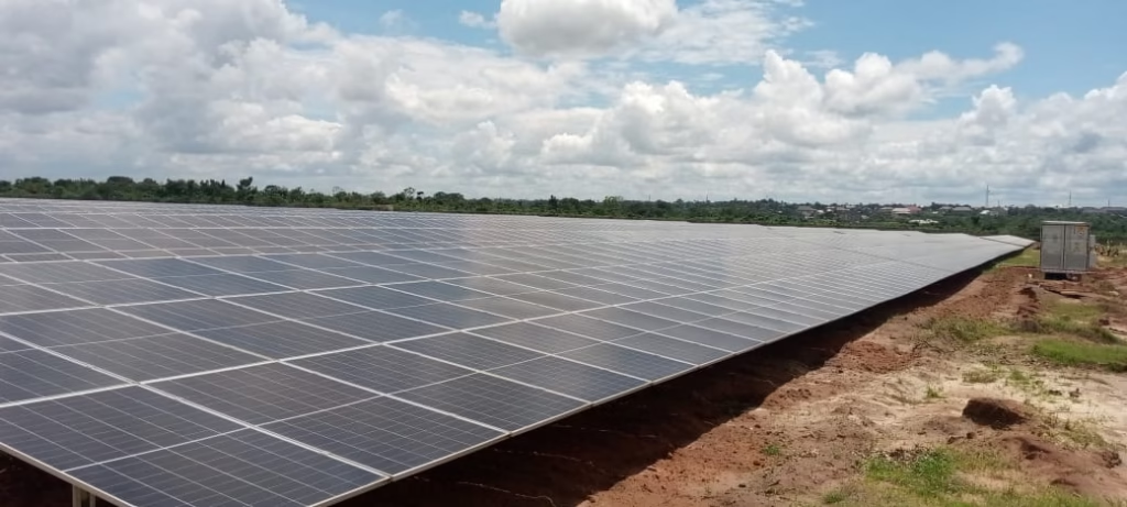
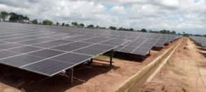
| Modules | 12,852 pcs | Total number of individual solar panels installed on site. |
| Transformer | 8 pcs | Step-up transformers that raise voltage for MV transmission. |
| Aux. Transformer | 7 pcs | Power internal loads like lighting, SCADA, control systems — not part of the main power export. |
| Parameter | Value | Explanation |
| Total DC Power | 8.546 MWp | Maximum power the PV panels can produce under standard test conditions. MWp = Megawatt-peak, a measure of DC capacity. |
| Total AC Power | 7.2 MVA | Combined output from inverters after converting to AC. MVA = Megavolt-Amperes, a unit of apparent power (used in AC systems). |
| STS (PV) | 7.5 MVA | Smart Transformer Station connected to PV inverters; it handles a maximum of 7.5 MVA. (2.5MVA each) |
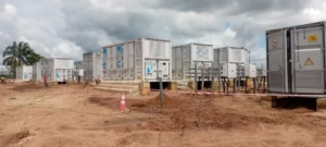
| BESS Size | 15.24 MWh | Battery Energy Storage System capacity: stores 15.24 megawatt-hours of energy. MWh = Megawatt-hour, measures energy (not power). |
| PCS Capacity | 6.0 MW | Power Conversion System for batteries; converts AC to DC (charging) and DC to AC (discharging). |
| STS (BESS) | 6.25 MVA | Smart Transformer Station for battery systems; rated at 6.25 MVA. (2.5MVA, 2.5MVA & 1.25MVA) |
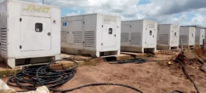
| DG Size | 3.75 MVA | Diesel generator size: provides backup power at 3.75 MVA. (625KVA each) |
| (STS (DG) | 4.0 MVA | Smart Transformer Station that handles DG output. (2MVA each) |
During commissioning of a solar hybrid project like (PV + BESS + DG), the main activities typically include:
- PV System Commissioning
- Continuity and insulation resistance tests on PV strings.
- String energization and IV-curve testing (to verify performance).
- Synchronization of string inverters (24 units) to the AC bus.
- Performance ratio (PR) and DC/AC efficiency checks.
- Transformer & Switchgear Commissioning
- Pre-commissioning tests on transformers (winding resistance, ratio test, vector group verification).
- Protection relay calibration and functional testing.
- MV switchgear energization and interlock verification.
- BESS Commissioning
- PCS (6 MW) functional tests for both charging and discharging modes.
- Battery racks installation check, communication with BMS.
- Step-by-step energization of battery banks.
- Capacity test to verify the 15.24 MWh rating.
- Safety checks: thermal management, fire suppression, alarms.
- Diesel Generator (DG) Commissioning
- Load test and synchronization with the MV bus.
- Black start test (to prove DG can start and energize the system in blackout).
- Fuel supply and control panel verification.
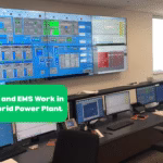
- Control & SCADA Integration
- Synchronization logic between PV, BESS, and DG through the Smart Transformer Stations (STS).
- Remote monitoring & control validation.
- Grid compliance tests (voltage, frequency ride-through, reactive power control).
- System Performance & Reliability Tests
- Island mode and grid-tied mode operation.
- Transition testing between sources (PV → Battery → DG).
- 72-hour reliability run at different loading conditions.
How the Battery Will Be Charged
BESS (15.24 MWh, with 6 MW PCS) can be charged in three main ways:
- From Solar PV (Primary Charging Source)
- During the day, excess solar generation (after meeting load demand or export limits) is routed to the PCS.
- PCS converts AC → DC and charges the battery.
- Example: If solar exports 5 MW and load is only 3 MW, the spare 2 MW charges the battery.
- From the Grid (if allowed by control logic)
- At night or during low solar production, the PCS can import grid AC power, convert it to DC, and charge the battery.
- Typically used in “time-of-use” or peak shaving strategies.
- From the Diesel Generator (Emergency Charging)
- If both solar and grid are unavailable (cloudy days + grid outage), the DG can supply AC through its STS.
- PCS converts it into DC to charge the battery, ensuring backup power availability.
- This is less efficient (and costly, due to fuel), so it’s usually last resort.
In summary:
- Commissioning covers step-by-step energization, protection checks, synchronization, and performance tests of PV, BESS, DG, and transformers.
- The battery charges mainly from solar PV, with grid and DG as backup charging sources, managed by the PCS and controlled through the Smart Transformer Station (STS).
1. From Solar PV → Battery Charging
- Flow Path:
PV Modules (DC) → String Inverters (AC) → MV Bus → PCS (AC/DC) → BESS (DC) - Explanation:
- Your solar modules produce DC power.
- String inverters (24 pcs) convert this DC to AC and inject it into the MV bus via the PV Smart Transformer Station (STS).
- When there is excess solar generation, the Power Conversion System (PCS) for the battery takes AC from the MV bus, converts it back to DC, and charges the battery racks.
- The BESS is directly connected to the PCS on the DC side.
- Cables Involved:
- DC Cables from PV modules → String combiners → Inverters.
- AC Cables (3-phase) from inverters → PV STS → MV bus.
- AC Cables (3-phase) from MV bus → PCS.
- DC Cables from PCS → Battery racks (BESS).
2. From Generator → Battery Charging
- Flow Path:
DG (AC) → DG STS → MV Bus → PCS (AC/DC) → BESS (DC) - Explanation:
- The diesel generator produces AC power.
- It feeds into the MV bus through its Smart Transformer Station (DG STS).
- The PCS then takes AC from the MV bus, converts it to DC, and charges the battery — exactly the same way it does with solar/grid power.
- The PCS controls the charging rate to protect the battery.
- Cables Involved:
- AC Cables from DG alternator → DG STS → MV bus.
- AC Cables from MV bus → PCS.
- DC Cables from PCS → BESS racks.
Simplified Connection Layout
PV DC —-> [String Inverters] —-> (AC) —-> PV STS —-\ \ DG (AC) —> DG STS ——————> (AC) —-> MV BUS —-> PCS —-> (DC) —-> Battery Racks / Grid (if allowed) ———————> Grid STS ——–/
- Key Point: Both PV and DG do not connect directly to the battery.
Everything goes through the PCS, which is the brain that converts AC ↔ DC and manages charging/discharging.
✅ So in short:
- Solar charging = PV → inverter (AC) → MV bus → PCS (DC) → Battery.
- Generator charging = DG (AC) → MV bus → PCS (DC) → Battery.
- The cables are: PV strings (DC), inverter AC feeders, MV bus cables, PCS AC input, and PCS-to-battery DC busbars/cables.
How the AC from MV Bus Feeds the PCS
- Yes — the AC from the MV bus passes through a Smart Transformer Station (STS) before it gets to the PCS.
- Each source (PV inverters, DG, Grid, BESS) has its own STS.
- The STS ensures safe voltage matching, protection, and switching before power enters/leaves the MV bus.
- Step-up or Step-down?
- PV Side:
- String inverters typically output low voltage AC (e.g., 400 V / 690 V).
- The PV STS steps this up to MV (e.g., 11 kV or 33 kV) so it can feed the MV bus.
- DG Side:
- Diesel gensets also produce low voltage AC (400–690 V).
- The DG STS steps this up to MV to match the MV bus.
- BESS Side (PCS):
- The PCS normally operates at low voltage AC as well.
- So the BESS STS steps down MV (e.g., 11/33 kV) to LV (400–690 V) before feeding the PCS.
- On discharge, the PCS converts DC→AC (LV) and the BESS STS steps it back up to MV for export.
- PV Side:
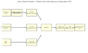
Simplified Charging Flow with Voltage Levels
- From PV to Battery:
PV DC → Inverter (AC LV) → PV STS (Step-up LV→MV) → MV Bus → BESS STS (Step-down MV→LV) → PCS (AC→DC) → Battery. - From DG to Battery:
DG (AC LV) → DG STS (Step-up LV→MV) → MV Bus → BESS STS (Step-down MV→LV) → PCS (AC→DC) → Battery.
✅ Key Point:
The MV bus acts like the central hub at medium voltage. Every source connects at MV using its own STS.
The BESS always needs its own STS because the PCS and battery are low-voltage devices — so charging requires step-down from MV → LV before AC reaches the PCS.
I’m interested in this work
I’m very happy to be one of the students in this course